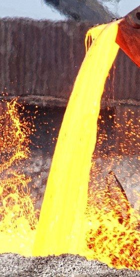
Slag at 1,250–1,550 °C
The risk of injuring people or destroying equipment is present at every single lift — not once in a while.
Thermal Eye Technologies
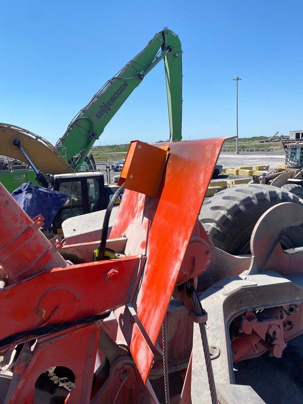
Thermal monitoring for slag pots. The camera measures the entire surface before the lift, the driver receives one unambiguous instruction, and every measurement leaves an auditable record.
Starting point
The risk of injuring people or destroying equipment is present at every single lift — not once in a while.
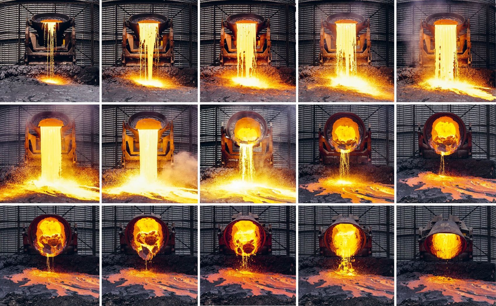
Pouring against the side wall carves out cavities. In the worst case a burn-through — and then it is not only slag leaving the pot, but molten steel.
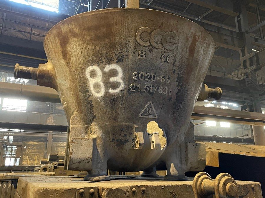
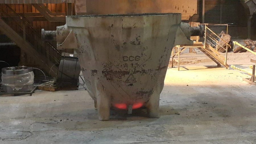
A handheld pyrometer covers a few points. The result ends up on paper, and after an incident there is nothing left to show what was actually measured.
The change
Today’s practice
Thermal Eye
How it works
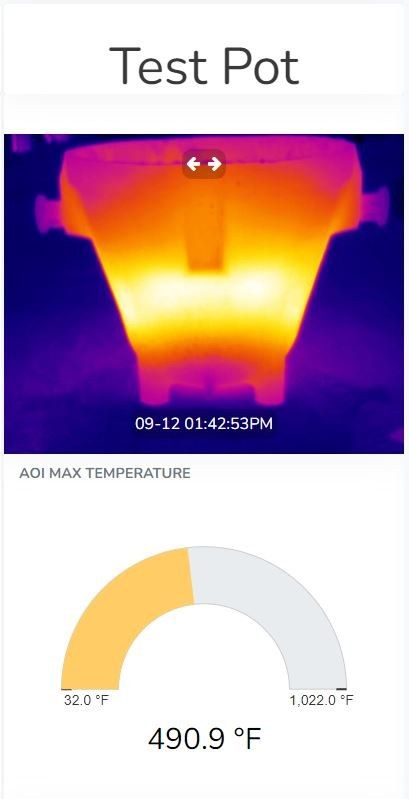
Measures the entire pot surface before the lift.
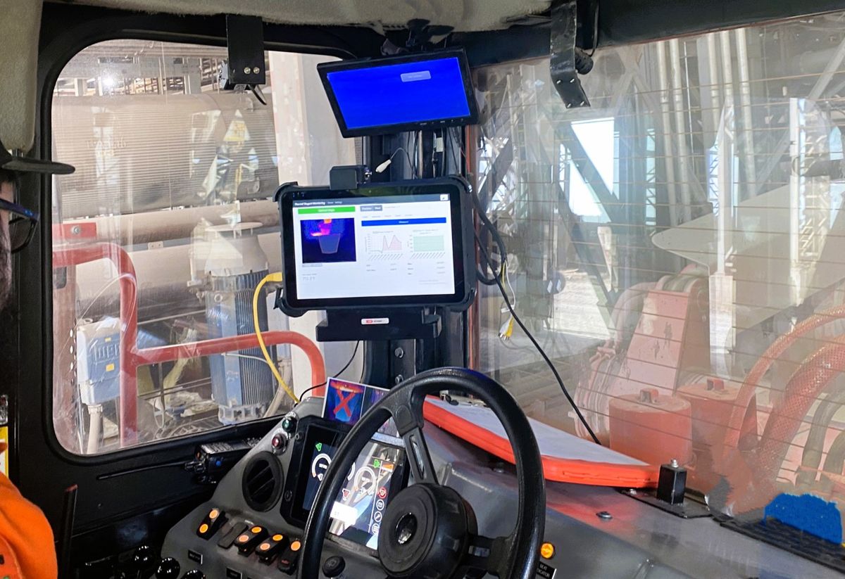
Evaluates the measurement right there in the vehicle.
One of four states on the in-cab display.
Record, media and the pot’s history.
The operator workflow has five steps, and at each one the only choices offered are the ones that make sense.
The upcoming AI module will perform this independent parallel audit automatically.
Measurement result
Temperature is OK
the pot may be lifted
Too hot — use it once
one more use, then inspection
Too hot — wait for cooling
do not lift, repeat the measurement
Danger — keep away
do not lift, call the supervisor
Safety is decided by the unfiltered radiometric maximum recorded across the whole cycle — not by the smoothed value on the display.
Auditable record
The raw record holds one temperature per pixel — not a picture. A measurement can still be recomputed a year later from the original data, with different thresholds than the ones running that day.
Fleet overview
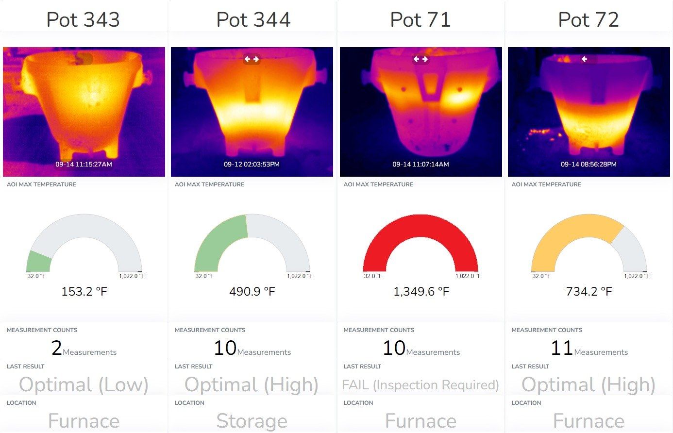
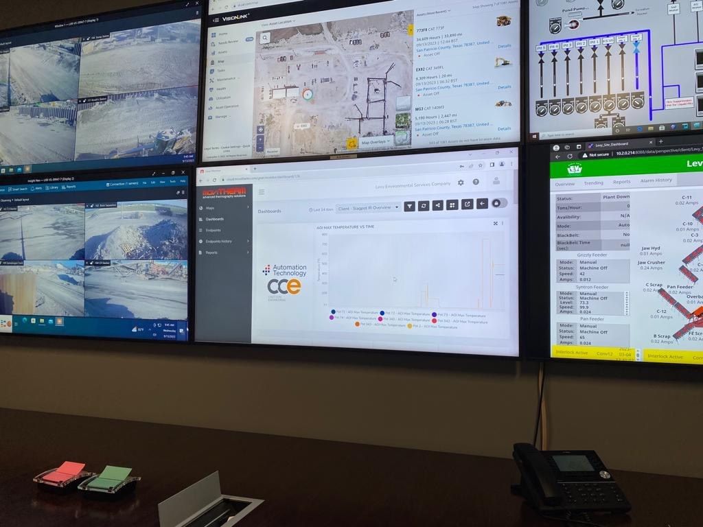
Thermal image and peak temperature in the monitored area, the number of measurements and the latest result.
Site and status — ready, in production, under repair, stand by, out of service.
Straight to the record — every card links through to the measurement, video included.
Platform
“Stored” means the server has read the record back and confirmed it.
Hardware
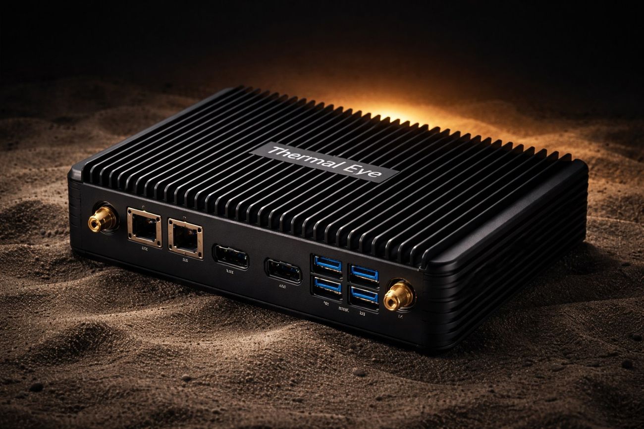
The tablet was replaced by a unit designed for this environment: no moving parts, no ventilation openings, connectors built for dust and vibration.
Operational resilience
UPS and two batteries
the main battery keeps the system alive ~10 min after a power loss, the backup up to a year in deep sleep (by design)
Controlled shutdown
the system first verifies the data is stored, then powers down camera, display and CPU in order
Automatic start
powers up as soon as supply returns, fixed peripheral sequence, log sent to the server
Alarm to the server
raised when the main battery drops below the configured threshold
BMS diagnostics
voltage, current, temperature, protection against overload, overheating and deep discharge
GPS and theft protection
location of the device and the vehicle
Service mode over USB
firmware and logs even with flat batteries
Service controls
START / STOP / RESET plus two programmable; every press is recorded
Replaceable batteries
connectorised, industrial — servicing without a soldering iron
Openness
Hikvision
ISAPI / RTSP
main industrial line
AT Sensors IRSX
GigE Vision, 640 × 512
radiometric channel
Demo mode
no hardware
training and demonstrations
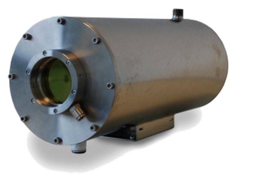
No vendor lock-in. The camera is chosen to suit the plant and the budget, not the software.
Roadmap
Designed in, shipping with version 2.0. Everything else on this page is version 1.0 and ships today.
Black-box mode
independent backup unit and backup communication
AI compute unit
evaluation and parallel audit directly in the vehicle
Measurement circuits
shock, tilt, acceleration, noise, motion wake-up
Next step
The pilot reveals the real temperature profiles of your pots. The thresholds are set from those — and only then does the fleet decision follow.
Contact e-mail and phone — to be added.